To properly display this page you need a browser with JavaScript support.
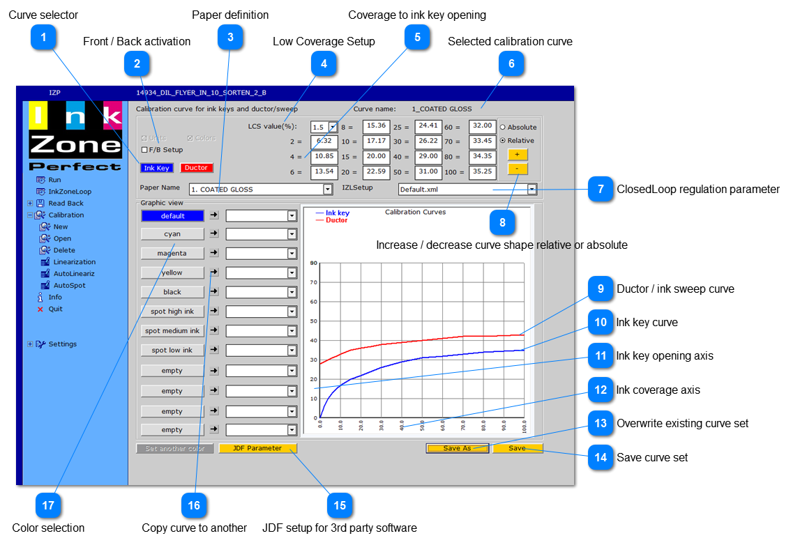
2.1.1. Calibration Curve - Base Window
Access the ink-preset calibration from the menu on the right.
Curve selector Select the curve to change by selecting either the Ink Key or Ductor button
Front / Back activation Activate the checkbox for web or perfecting press setup in order to define an individual ink preset curve each each side
Paper definition Set the ISO paper type definition 1 to 8.
Low Coverage Setup Setup the ink key opening for low plate coverage area (coverage on plate is below 2%)
Coverage to ink key opening Translation table between ink coverage on plate (left column) and ink key opening (right column)
Selected calibration curve Calibration curve name
ClosedLoop regulation parameter Each calibration curve set is linked to a InkzoneLoop regulation setup. A InkZoneLoop regulation is setup is created in the IZLoop screen through the button "Job", "Setup".
Increase / decrease curve shape relative or absolute Change all curve points through the plus and minus button at once. Choose between absolute or relative change
Ductor / ink sweep curve Setup the ductor/sweep calibration with the red curve
Ink key curve Setup the ink key calibration with the blue curve
Ink key opening axis The Y axis represents the transferred ink key opening from 0 to 100%.
Ink coverage axis The X axis represents the ink key coverage from 0 to 100 % from the CIP3 data file
Overwrite existing curve set Overwrite an existing calibration curve set.
Save curve set Stores calibration curve set.
JDF setup for 3rd party software Link a JDF parameter set to the curve setup. The JDF is used to setup new jobs within X-Rite or Techkon software.
Copy curve to another Copies an existing calibration curve, ink-key or ductor, to another color. First select source and target curve. Then press the arrow button in between.
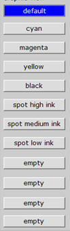
Color selection Choose an ink calibration curve from the color list.